NSGG UXO Test Site
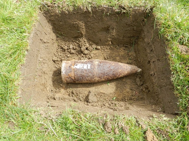
The 2013 Near Surface Geophysical Group (NSGG) field exhibition focused on the detection and interpretation of Unexploded Ordnance (UXO) through a series of geophysical techniques. A 20m² area of the NSGG test site was seeded with 16 carefully selected geophysical targets. Among these, five were inert UXO items, which were later removed and replaced with objects having similar geophysical properties to ensure a consistent testing environment.
The remaining targets were chosen to represent a variety of materials and objects, each producing different geophysical responses. These targets were specifically selected because they were not detectable by all common UXO detection instruments, such as magnetometers or gradiometers, transient electromagnetic systems, or ground-penetrating radar (GPR). However, each target was detectable by at least one of the geophysical methods being tested in the exhibition. This approach allowed for a comprehensive evaluation of the effectiveness of different detection techniques and their ability to distinguish between UXO and non-target objects in a real-world setting.
The diversity of the targets and the inclusion of objects with similar geophysical signatures to UXO items emphasized the importance of using a multi-method approach in UXO detection, ensuring a higher probability of identifying potential threats in varied environmental conditions.

On May 18, 2013, an initial survey was conducted over the seeded area using a G-858 caesium gradiometer, Mala X3M Ground Penetrating Radar system, and an EM61MK2 time-domain metal detector.
These datasets form the master datasets, which define the signature of each buried target. Plots of the master datasets can be viewed through the following links: Electromagnetic, Ground Penetrating Radar, and Magnetics.

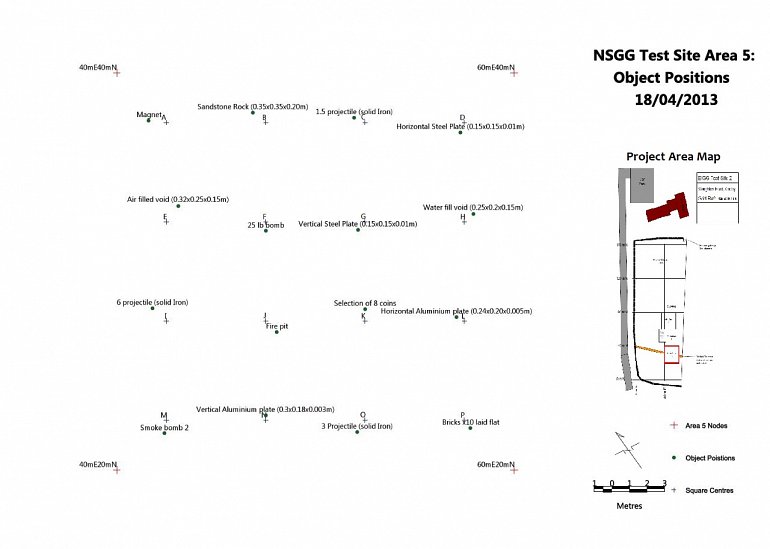
The careful planning of the target positioning in the 2013 NSGG field exhibition was essential to ensure that each geophysical anomaly could be fully resolved during the survey. By placing the targets at well-defined locations relative to one another, the survey ensured that each target’s signature could be distinctly detected and analyzed using the standardized data acquisition procedures for each technique. A tabulated description of each target, including its relative position (expressed in the local coordinate system established at the NSGG test site), size, and depth of burial, is provided below.
| Table1 : Positioning of Objects within TS2 Sub Area 5 | ||||||||
|---|---|---|---|---|---|---|---|---|
| # | Square | Easting | Northing | Easting | Northing | Depth (m) to top of feature | Depth (m) to bottom of feature | Object Description |
| 1 | A | 42.5 | 37.5 | 41.6 | 37.6 | 0.3 | 0.31 | Magnet |
| 2 | B | 47.5 | 37.5 | 46.85 | 38 | 0.13 | 0.33 | Sandstone Rock (0.35×0.35×0.20m) |
| 3 | C | 52.5 | 37.5 | 51.95 | 37.75 | 0.23 | 0.28 | 1.5” projectile (solid Iron) |
| 4 | D | 57.5 | 37.5 | 57.3 | 37 | 0.22 | 0.23 | Horizontal Steel Plate (0.15×0.15×0.01m) |
| 5 | E | 42.5 | 32.5 | 43.1 | 33.3 | 0.15 | 0.3 | Air filled void (0.32×0.25×0.15m) |
| 6 | F | 47.5 | 32.5 | 47.5 | 32.05 | 0.03 | 0.4 | 25 lb bomb |
| 7 | G | 52.5 | 32.5 | 52.15 | 32.1 | 0.15 | 0.3 | Vertical Steel Plate (0.15×0.15×0.01m) |
| 8 | H | 57.5 | 32.5 | 57.95 | 32.9 | 0.3 | 0.45 | Water fill void (0.25×0.2×0.15m) |
| 9 | I | 42.5 | 27.5 | 41.8 | 28.15 | 0.15 | 0.3 | 6” projectile (solid Iron) |
| 10 | J | 47.5 | 27.5 | 48.05 | 26.95 | 0.3 | 0.3 | Five pit |
| 11 | K | 52.5 | 27.5 | 52.5 | 28.1 | 0.05 | 0.05 | Selection of 8 coins |
| 12 | L | 57.5 | 27.5 | 57.1 | 27.7 | 0.2 | 0.2 | Horizontal Aluminium plate (0.24×0.20×0.005m) |
| 13 | M | 42.5 | 22.5 | 42.4 | 21.85 | 0.1 | 0.15 | Smoke bomb 2” |
| 14 | N | 47.5 | 22.5 | 47.5 | 22.75 | 0.1 | 0.28 | Vertical Aluminium plate (0.3×0.18×0.003m) |
| 15 | O | 52.5 | 22.5 | 52.1 | 21.9 | 0.2 | 0.28 | 3” Projectile (solid Iron) |
| 16 | P | 57.5 | 22.5 | 57.8 | 22.1 | 0.25 | 0.33 | Bricks ×10 laid flat |
Since the seeded area was established in May 2013, the data archive has expanded significantly, now including 10 different datasets covering 4 geophysical techniques and equipment from 8 different manufacturers.
As of July 10, 2013, all UXO targets were removed and replaced with targets of equivalent material properties. Additional data acquisition was then conducted to assess the signatures of the new targets. While this data has not yet been processed, it is expected that it will be added to the website in due course.
| Table2 : Replacement UXO Targets TS2 Sub Area 5 | |||||||||
|---|---|---|---|---|---|---|---|---|---|
| # | Square | Easting | Northing | Easting | Northing | Depth (m) to top of feature | Depth (m) to bottom of feature | Original Object | Replacement Object |
| 3 | C | 52.5 | 37.5 | 51.95 | 37.75 | 0.15 | 0.22 | 1.5” projectile (solid Iron) | 2 × Scaffold brackets 0.06DIA ×0.15m(0.5Kg) |
| 6 | F | 47.5 | 32.5 | 47.5 | 32.05 | 0.15 | 0.39 | 25 lb bomb | Casserole pot 0.2mDIA x0.1m (1Kg) |
| 9 | I | 42.5 | 27.5 | 41.8 | 28.15 | 0.1 | 0.25 | 6” projectile (solid Iron) | Oxy Acetylene canister 0.52mDIA x 0.17m 13.9Kg |
| 13 | M | 42.5 | 22.5 | 42.4 | 21.85 | 0.1 | 0.15 | Smoke bomb 2” | Spray Can 0.07mDIA×0.15m 0.125Kg |
| 15 | O | 52.5 | 22.5 | 52.1 | 21.9 | 0.18 | 0.25 | 3” Projectile (solid Iron) | Aerosol canister 0.07mDIA x0.26m 0.25Kg |
Further Information
For further information on the NSGG test site please refer to the www.nsgg.org.uk.
The archived datasets for this resource are held by Geomatrix. For access to these resources please contact sale@geomatrix.co.uk.
